On this page
To repair STL file errors, identify the defect, apply a small repair, and compare the exported result with the original before slicing it again. Start with your slicer's available repair function for simple problems. Move to a dedicated service or mesh editor when errors persist or the repair changes a feature you need. A clean mesh report and a correct layer preview answer different questions; check both before committing to a print.
This workflow starts with an existing STL, a copy of the original, and a slicer configured for your printer. Record the part's intended dimensions and any holes, cavities, mating surfaces, or fine details that must survive. The goal is a repaired file whose changes you can explain and whose sliced output matches the part you intended to make.
Turn your repair checklist into a print-prep app
When you handle several models, build a place to keep the original file, repair report, preserved features, and slicing decision together. In Atoms, describe that print-prep app in plain language, build its dashboard and job pages, and add login and stored review records. The workflow below gives you the checks to put in the app; the complete build prompt later in this article turns them into a concrete specification.
Build a print-prep app to organize model uploads, repair checks, and reviewed results.
Step 1: Identify the error and protect the original
Save an untouched copy before running STL repair. Name the working copy separately, and keep the warning message or diagnostic report alongside it. This gives you a reference when a repair looks convincing but changes the model.
Start STL file repair by inspecting the problem area in the model view. A missing face leaves an opening in the surface. A designed passage through a part can have complete walls around it. Close an accidental gap, and preserve an intentional opening.
Use this triage table to decide what to inspect next:
| What you observe | First check | What would make you reject a repair? |
|---|---|---|
| A hole or missing face warning | Locate the open surface boundary | The repair caps an intended passage |
| Faces pointing the wrong way | Inspect face orientation | Adjacent faces remain inconsistent |
| Overlapping or tangled geometry | Inspect the intersection region | A repair changes the shape you need |
| Loose fragments | Identify which components belong to the part | A small intentional component disappears |
| A feature missing in the layer preview | Compare the exported geometry and slicing settings | The repaired mesh has lost that feature |
Write a short preservation note before proceeding. For a bracket, that might mean keeping the mounting holes open and the mating face flat. For a hollow ornament, it might mean retaining the interior cavity and drain opening. The note turns a vague judgment that the model “looks fine” into a check you can repeat.
Step 2: Use the smallest effective STL repair
Choose a repair method based on the defect and the access you have. Keep each attempt as a separate file so that you can compare results without losing the original.
Try the slicer's available repair first
Prusa's documentation says PrusaSlicer repairs some model problems automatically, while other files need a dedicated tool. Import the working copy and inspect both the warning and the resulting slice. If the slicer resolves the problem and preserves your intended geometry, you have a candidate for the later acceptance checks.
Repair options vary with the application, operating system, and version. Prusa's article describes a Windows 10 Netfabb integration; check the options actually present in your installation before following that route. If the documented command is unavailable, use an accessible dedicated repair tool.
Use an online service for files you can upload
Formware offers free online STL repair and accepts binary and ASCII STL files. Its website says files are deleted after download or, otherwise, after six hours. Check that this upload-and-retention arrangement fits the file owner's requirements before sending a design.
Upload the working copy, wait for the result, and download the repaired file under a new name. Keep any diagnostic information the service provides. A downloaded file still needs the geometry comparison and slicing checks below.
If your design must stay on your machine, choose a local workflow.
Use Fusion when you need to inspect repair choices
Fusion's repair controls expose useful differences between a local fix and a reconstruction. In the Design workspace, open the Mesh tab, choose Prepare > Repair, and select the mesh body. Autodesk's instructions describe the available operations and their consequences.
Start with Close Holes when the problem is a missing surface or flipped triangles. Use Stitch and Remove when the repair also needs to join triangles or remove duplicate faces, degenerate faces, or small shells. Review the preview before committing the operation, especially when a small shell might be an intentional part.
Autodesk documents Wrap and Rebuild as operations that destroy internal structures. Reserve them for situations where that consequence is acceptable. A hollow part or a model with important internal channels needs particular care before taking either route.
Expand Detailed Analysis to compare the issues before and after the selected settings. Toggle Preview to see the original and proposed result. Record the operation that you chose, then save and export a separate repaired copy for checking.
Handle face orientation as a specific defect
In Blender, the Face Orientation overlay helps identify incorrectly oriented faces. In Edit Mode, Mesh > Normals > Recalculate Outside adjusts the selected faces' orientation, as described in the Blender manual. Inspect the result around cavities and connected surfaces. Reorienting faces addresses orientation; missing faces require their own repair.
Step 3: Compare the repair with the original
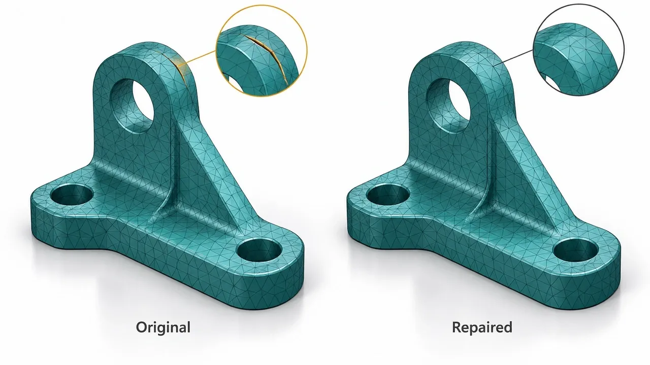
AI-generated illustration of preserving functional openings during repair; not the measured cube fixture or a validated STL file.
Inspect the changed region before relying on the headline status. Compare overall dimensions, intentional openings, internal structures, separate components, and fine detail. Use the same scale and view when switching between the original and repaired versions.
A small synthetic example shows what an understandable repair report looks like. We created a cube with a bounding box from 0 to 20 on each axis, removed one known triangle, and restored that exact triangle from the original definition. The reported dimensions assume millimeters. A separate edge-count check read the exported ASCII STL files and counted how many triangles shared each geometric edge.
| Check on the synthetic cube | Missing-face file | Restored-face file |
|---|---|---|
| Triangle count | 11 | 12 |
| Edges used by only one triangle | 3 | 0 |
| Edges used by more than two triangles | 0 | 0 |
| Bounding-box dimensions | 20 × 20 × 20 | 20 × 20 × 20 |
The added triangle closes the known gap without changing the bounds. This is a measured teaching fixture with a known correction, rather than a test of an automatic repair service. The edge check covers edge incidence and shared-edge orientation. It does not check self-intersections, vertex manifoldness, slicer output, or a printed part.
For your own file, look for the same chain of explanation: a located defect, a recorded operation, a visible change, and a relevant check. A lower error count is useful evidence, but it must be paired with preserved geometry.
Matching bounding boxes alone are weak evidence of detail preservation. A repair could retain the outer dimensions while changing an internal opening. Compare the features from your preservation note directly, using measurements or cross-sections where your software supports them. Set acceptable dimensional changes from the part's function and mating requirements.
Step 4: Reimport and inspect the sliced layers
Open the exported repair in a fresh slicer project. This checks the file you will actually use, rather than a repair tool's in-memory preview. Confirm the scale, orientation, and selected printer settings before slicing.
Move through the layer preview around the repaired region. Inspect the first appearance of the feature, its middle, and its final layers. Check that the intended opening remains open, walls follow the expected shape, and separate parts remain separate where the design requires it. When a feature disappears, compare the mesh itself with the preview to identify whether the change happened during repair or slicing.
Use this acceptance checklist before starting the job:
- The exported file opens and the relevant mesh warnings are resolved or understood.
- The dimensions and critical features match the preservation note.
- The layer preview contains the intended walls, openings, and components.
- You can explain which repair operation changed which region.
- Any feature whose physical fit matters has a suitable test-print plan.
If a mating feature changed, check that feature in a small physical trial before printing the full assembly. Mesh validation can help establish the geometry's consistency; physical fit also depends on the printing process.
If the STL still fails
Return to the original and isolate the remaining problem. Change one repair operation at a time, then export and compare again. Repeatedly repairing a file that has already lost its intended shape makes the reference harder to recover.
If automatic repair cannot recover an ambiguous surface, edit the source model or obtain a corrected export from its author. When a reconstruction removes an important cavity, return to a method that preserves it or rebuild that feature deliberately in the source design. Prusa's documentation notes that different repair methods can succeed on different models, so a failed attempt is a reason to inspect the defect and method together.
Build your print-prep app with Atoms
Build an app around the decisions you now know how to make. Atoms creates websites and web applications from natural-language instructions, with user login, data storage, deployment, and code export. For a print studio, that gives each job a home: who submitted it, which features matter, what changed, and who accepted the result.
Use these capabilities to make the review process easier to repeat:
- Build the intake and review pages: describe the fields, workflow, and appearance, then refine the result through conversation.
- Keep review records in one app: use login and stored data to organize jobs, preservation notes, and acceptance decisions.
- Improve the app as you work: ask for focused changes to report layout, filters, and review steps, and export the code when you need to extend it.
For automatic geometry repair, connect a mesh engine you have tested on representative files. Show the engine's measured outputs, failures, and unchecked properties in the report. Keep a “Ready to slice” decision separate from the tool's repair status so that your app preserves the acceptance checks from this tutorial.
Copy this complete build prompt
Paste this brief into Atoms to start your own app. The button opens the existing Atoms entry; copy the prompt and paste it after signing in.
Copy this brief, open Atoms, and build a print-prep app around your review workflow.
Read the Atoms Cloud introduction for the application's storage and backend planning, then narrow the first version to one repair method and a report you can verify.
Conclusion
Accept the smallest repair that resolves the defect, preserves the features you need, and passes a fresh slicing check. Keep the original file and the evidence for that decision so you can trace a failed print back to its source.
Bring the preservation checklist, reports, and reviewer decisions into one app. Start building in Atoms, paste the brief above, and adapt the intake fields and review steps to the models you actually handle.
Keep your model files, repair evidence, and slicing decisions together in an app built for your studio.
Frequently asked questions
01Q1: Does a successful STL repair prove the model will print correctly?
It establishes only the checks that the repair tool performed. Inspect the exported geometry and sliced layers separately, and use a physical test when fit or function needs confirmation.
02Q2: Can I repair an STL file online for free?
Formware currently offers a free service for binary and ASCII STL files. Check its file-handling information and your permission to upload the design, then validate the downloaded result.
03Q3: Should every hole be filled?
Close accidental gaps in the surface. Preserve designed passages and cavities, whose surrounding geometry can be complete even though they appear open from a particular view.
04Q4: What does a changed triangle count tell me?
It tells you that the mesh's triangulation changed. In the synthetic cube example, one restored triangle closed the known gap. For a complex model, inspect the changed regions and intended features to determine whether the change was acceptable.
